Testing of embedded firmware is too complicated. An enormous amount of resources are required for a system test that does not detect enough errors. Open loop testing is a new approach to hardware/software integration testing that saves development time and costs.
With embedded firmware, correct handling of the microcontroller peripherals (GPIO, I2C, …) is crucial. Drivers are specially programmed for this. Open loop tests can perform detailed checks on these drivers.
The term “open loop” comes from the control engineering sphere. The purpose of control engineering is to create the desired state at the output, by influencing the actual process. Closed loop controllers measure the output constantly. The discrepancy between the setpoint and the actual state is used to calculate a control action. Open loop controllers control a process “blindly”; in other words, they are not dependent on the current condition of the system, which makes handling easier.
Embedded systems are usually tested in a similar way to closed loop controllers. But the complexity of testing can be reduced tremendously with open loop principles. The tests become compact and comprehensible.
In this article, I will begin by describing the state of the art in the testing of embedded systems. After that, I will explain the relationship to closed-loop systems. Finally, we will develop an alternative approach, using open loop principles.
State of the Art in Testing
Our example will be an embedded system for the speed control of a motor. This system:
- is based on a microcontroller,
- receives via CAN messages with a setpoint speed,
- controls power electronics via PWM, in order to supply the external motor,
- receives impulses via a rotary encoder, from which the setpoint speed can be calculated,
- contains an internal temperature sensor that switches the system off if it overheats.
A typical requirement could be formulated as follows:
- If a speed of 100/min is transmitted via a CAN message, the system must have reached a speed of between 98 and 102 rpm within 2 seconds.
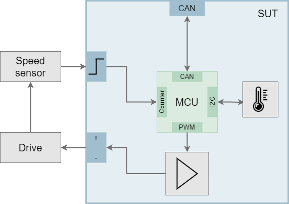
In order to test this requirement automatically, a test stand must be set up. The following graphic shows the structure of such a test stand.
The test system must simulate an encoder signal for the embedded system (System Under Test, SUT). For this purpose, a motor must be simulated electrotechnically, based on the +/- signals. The SUT inputs are thus dependent on the SUT outputs. This closed loop characterises every closed loop system. The test is evaluated as a “pass” or a “fail”, based on the output.
This way, the desired system test can be carried out automatically. But there are still several problems that could arise.
- If an error occurs, the cause cannot be determined. Possible causes are the embedded firmware, the hardware (board) or perhaps even a faulty simulation in the test system.
- The test only checks the system for a single condition. For example, it cannot indicate that the PWM generation on the microcontroller is working correctly for all possible duty cycles.
- The internal temperature sensor is not part of the test interface. In order to test the temperature cut-off function, the test stand can be supplemented with a heating system. But even then it is not possible to check how the system reacts to something like a faulty sensor.
- Every test stand must be specifically set up for the actual requirements of the element to be tested.
Generally, all these problems can be traced back to one fundamental limitation of closed loop testing: the SUT has many internal state variables that are not visible externally. All the test can do is attempt to produce as many of these internal states as possible through “suitable” selection of input variables.
Open Loop Testing
In an open loop test, the need to test internal state variables is eliminated. In the system test, the aim of the test is the entire circuit board. Only the microcontroller is considered in the proposed open loop test.
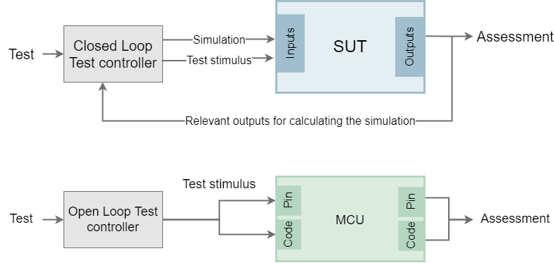
The purpose of this test is to check that the PWM driver is functioning correctly. The test system controls the PWM driver with a duty cycle. The microcontroller sends a PWM signal at a pin. The test then checks whether the signal has the desired duty cycle and evaluates it as a “pass” or a “fail”.
The open loop structure is apparent immediately: there is no loopback from the outputs to the inputs of the microcontroller.
Microcontroller inputs can be tested in the same way. An electrical signal is generated by the test system. The signal reproduces the impulses from the encoder. The speed that is measured can then be read out from the microcontroller.
The microcontroller runs firmware that contains all of the subcomponents to be tested in an unchanged form. There is an interface to the code which allows these subcomponents to be controlled and read out externally. Thus, the test that is shown here can be considered a so-called hardware-software integration test.
This structure has a number of advantages:
- By focusing on one component, the complexity of each test case is low. The tests are compact and therefore easy to read. If a test fails, the cause can be identified immediately.
- Each component can be systematically tested for every imaginable input value.
- Internal error states that are not attainable in a system test, can be tested. For example, the behaviour of the drivers can be tested in case of an overload of the CAN bus or a temporary electrical disturbance of the I2C communication.
- Tests are performed at the pin level of the microcontroller. The pin behaviour is standardised for most of the available peripherals.
- The test system can be reused for different DUTs.
Summary
System tests must always provide both a simulation of the environment and the test stimulation. This means that a closed loop structure is essential. With open loop tests, this is not necessary, as they can be designed as integration tests. Here, the test stimulus specifies the pin behaviour or calls up functions in the code.
The open loop principle presented here enables the formulation of HW-SW integration tests. These tests can check subcomponents of the system under every imaginable condition. Such testing is not economically viable with system tests.
Open loop testing can contribute to the practical implementation of the test pyramid that is often proposed for embedded systems.


