Open Loop Tests have the potential to revolutionise firmware development.
This article describes a technical approach to implementing such tests. Curious readers can try out the results directly in your browser.
Requirements
Open Loop Tests are characterised by three aspects.
- The Device Under Test (DUT) is the microcontroller.
- The tests access the microcontroller pins directly.
- There is no simulation of the DUT environment.
You can determine the requirements for an Open Loop Test system using these three aspects.
It is often not possible to run firmware without the anticipated environment. Let’s assume, for example, that production data is stored in an EEPROM on the circuit board. This data is read when the firmware is initiated. But in the context of an Open Loop Test, there is no EEPROM; thus, an error would occur.
Therefore, Open Loop Tests work with a specific version of the firmware, which includes only the software components to be tested.
Writing Drivers that set output pins
The first structure image shows the testing of a pulse driver.
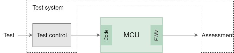
The MCU driver must generate a HIGH level at the pin for a desired period. The driver will provide the necessary C-function.
void Generate_Pulse(uint32_t length_us);
The Open Loop Test needs to have two options here:
- Functions to call up on the DUT
- Physical signals to evaluate.
Drivers that read inputs pins
The second structure image shows the testing of a counter driver.
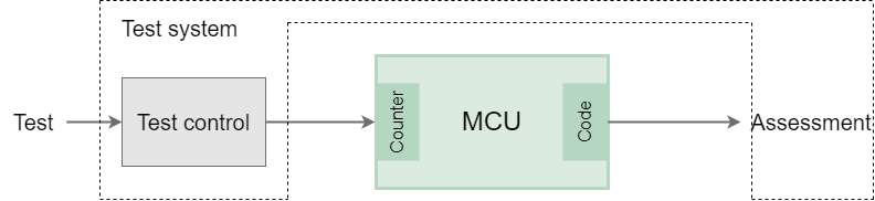
Here, the order is reversed. The Open Loop Test must be connected to a pin pulse. The MCU periphery counts the pulses, then a driver provides a function to enable the counter to be read.
uint32_t Counter_Read();
void Counter_Reset();
Here too, the Open Loop Test must be able to
- generate physical signals,
- call up functions on the DUT and process the return values.
That covers the most important requirements for an Open Loop Test system.
Our Solution
The ExecutionPlatform was developed as a test device for Open Loop Tests. An individual ExecutionPlatform is built into the desired microcontroller (MCU). The method of use and the test options are uniform for all MCUs.
So-called endpoints serve as an interface between the test and the periphery functions. Via a code interface, tests can call up functions on the MCU and evaluate the return values. The Robot Framework is used for the test sequences. The endpoints and the code interface from the test sequences are used.
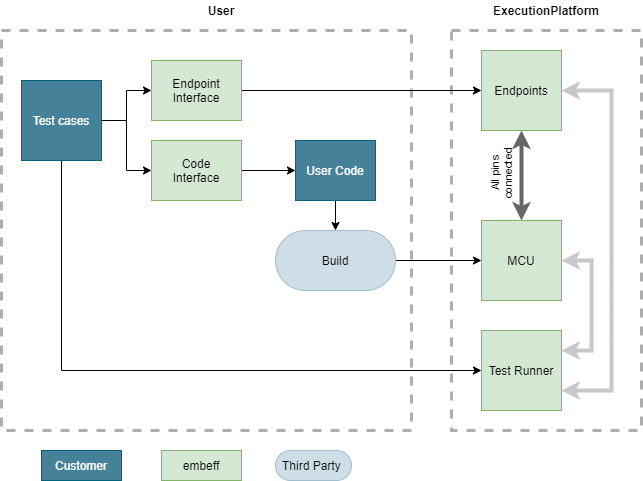
Endpoints
Each endpoint supports a specific periphery (CAN, UART, ADC, …). The periphery function can refer to one or more MCU pins, as required. The endpoints can be configured on the test device as desired. All of the MCU pins are available for such tests.
For example, the GPIO endpoint can read and generate signals. The endpoint is configured for one specific MCU pin.
On the other hand, the SPI slave endpoint behaves like a complete SPI module in slave mode. The endpoint reads the data sent by the MCU. The data can be read out in the test. Responses to be sent from the test can be set in advance. This endpoint is configured for 3 MCU pins (MISO, MOSI, SCK) and, if you wish, a chip select line can also be configured.
The endpoints that have been configured can be used directly from the test sequence. The GPIO endpoint can also measure times.
*** Test Cases ***
Generate 2us Pulse and check that it is between 1.9us and 2.1us
    ${measurementId} =  GPIO Measure Between Rising And Falling Edge  PB4  PB4
    # TODO: Call driver to generate pulse for 2us on PB4?
    ${pulse_ns} =  GPIO Get Measurement Result In Ns  ${measurementId}
    Should Be True  1900 < ${pulse_ns} and ${pulse_ns} < 2100
In this example, the time between the rising and falling edge can be measured at Pin PB4. The pulse driver must also be called up via the code interface in order for the MCU to generate a pulse.
Code Interface
Functions on the DUT are called up during the run-time, via the code interface. The functions that can be called up must be registered in the firmware, via a mechanism that is also supplied.
#include <ep/core.h> // Provides ep_register and ep_process_loop

int32_t square(uint8_t const* payload, int len) {
    int num = atoi(payload);
    return num*num;
}

int ep_app_main() {
    ep_register("square", &square);
    return ep_process_loop(); // Blocks and processes calls to the code interface
}
From the test sequence, the registered functions can be called up using the keyword ‘DUT Invoke’.
*** Test Cases ***
Invoke Square With 3 Gets 9
    ${res} =  DUT Invoke  square  3
    Should Be Equal    ${res}
A practical example
A typical test uses endpoints and code interface together:
*** Test Cases ***
Generate 2us Pulse and check that it is between 1.9us and 2.1us
    ${measurementId} =  GPIO Measure Between Rising And Falling Edge  PB4  PB4
    DUT Invoke  Generate_Pulse 2
    ${pulse_ns} =  GPIO Get Measurement Result In Ns  ${measurementId}
    Should Be True  1900 < ${pulse_ns} and ${pulse_ns} < 2100
You want to see this example in practice? Then take a look at this detailed blog post. It describes how to test a pulse generation driver on a STM32 microcontroller. You can also jump right to it and play around with open loop tests in your browser.