This article describes how automatic tests for the SPI communication of a STM32 look in practice. The result are automatic hardware/software integration tests for this microcontroller.
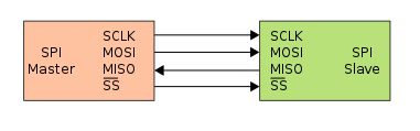
SPI is a widely used in embedded systems. For example a sensor might be connected to the MCU with SPI. In this case, the MCU is acting as a master (initiating the communication) and the sensor is acting as a single slave (reacting to the communication).
To ensure data integrity, a sensor might append a checksum to its data. This way, the microcontroller can evaluate the checksum and detect corruption. Modern microcontroller like STM32 already support this in hardware.
We will explore how the STM32U5 MCU driver for such a scenario looks and how it can be tested with our SPI-Slave Endpoint.
SPI basics
It is important to keep in mind the basic principle of SPI. The master controls the clock SCLK and sends data on MOSI. Each clock cycle one bit is transferred to the slave. At the same time, on each clock cycle a bit is read from the slave on MISO. This means reading and writing happen simultaneously.
Let’s get back to our sensor example. Assume the sensor returns a 32 bit measurement value. To read this value, you have to “write” 4 bytes. You are only interested in the return value here, so you can send just zeros.
MOSI 0x00 0x00 0x00 0x00
MISO 0x61 0x62 0x63 0x64
This way, the master will receive 0x61 62 63 64 (which is “abcd” encoded in ascii).
Checksums
CRC is a common way to calculate a checksum. There are a lot of different implementations which vary in their length (8-bit, 16-bit, 32-bit), their polynomial and other parameters.
In the datasheet of our sensor, we find the information that it appends its data by a CRC-8-CCITT checksum. crccalc.com is a convenient website to calculate/compare checksums. For our “abcd” input above, it says the checksum is 0xA1.
If we want to read the data (4 bytes) and the checksum (1 byte), we need to transmit 5 bytes to the sensor. If everything is right, the communication should look like this.
MOSI 0x00 0x00 0x00 0x00 0x00
MISO 0x61 0x62 0x63 0x64 0xA1
Driver with CRC support
Enough theory, let’s start implementing it for our STM32U5! We will use STM32CubeMX as a starting point. But first, we need to check the hardware support. The reference manual tells us on page 2425 that received SPI data can be evaluated against a CRC error:
CRC error (CRCE) This flag is used to verify the validity of the value received when the CRCEN bit in the SPI_CFG1 register is set. The CRCE flag in the SPI_SR register is set if the value received in the shift register does not match the receiver SPI_RXCRC value, after the last data is received (as defined by TSIZE).
That looks promising. To enable this in the CubeMX driver, we need to change the default initialization of our SPI1 driver a bit:
    hspi1.Init.CRCCalculation = SPI_CRCCALCULATION_ENABLE;
    hspi1.Init.CRCLength = SPI_CRC_LENGTH_8BIT;
    hspi1.Init.CRCPolynomial = 0x107;
Next, we need to prepare a send function with support for error detection:
int32_t transmitData(uint8_t const* payload, int len){
    // Returns 1 if CRCE is detected, 0 otherwise.
    uint8_t rxBuffer[100];
    HAL_SPI_TransmitReceive(&hspi1, (uint8_t*)payload, rxBuffer, len, 200);
    return (hspi1.ErrorCode & HAL_SPI_ERROR_CRC) != 0;
}
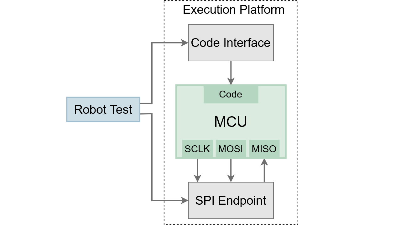
In the next step, we want to test this function automatically. We register it to make it accessible through the Code Interface.
ep_register("transmitData", &transmitData);
Automated tests with the SPI Endpoint
Now we can work on the fun part: Automated Testing. The test objective is our transmitData function and its CRC handling.
In our Open Loop Test the SPI Endpoint replaces our sensor. To test the CRC handling, we use the Endpoint to respond with pre-defined data to the MCU transmit.
In the first test, we respond with the proper CRC value (0xA1). The test assert is that the transmitData function returns 0. The transmitted value is not important here, we just need to clock out 4 bytes to read 4 bytes.
*** Test Cases ***
DUT signals no error when correct crc is received
    SPI1 Set Response Bytes    abcd\xA1
    ${hasReceiveError} =    Dut Invoke    transmitData    0000
    Should Be Equal As Integers    ${hasReceiveError}    0
In the next test, we change the data but use the same CRC response. We assert that the MCU driver detects this CRC mismatch and transmitData returns 1.
*** Test Cases ***
DUT signals error when wrong crc is received
    SPI1 Set Response Bytes    a00d\xA1
    ${hasReceiveError} =    Dut Invoke    transmitData    0000
    Should Be Equal As Integers    ${hasReceiveError}    1
At last, we can run the tests:
==============================================================================
Spi With Crc :: Test the stm32u5 CRC hardware integrated in SPI.
==============================================================================
DUT signals no error when correct crc is received                     | PASS |
------------------------------------------------------------------------------
DUT signals error when wrong crc is received                          | PASS |
------------------------------------------------------------------------------
Spi With Crc :: Test the stm32u5 CRC hardware integrated in SPI.      | PASS |
2 tests, 2 passed, 0 failed
==============================================================================
Both tests pass. So we know that the MCU hardware is indeed evaluating the CRC byte properly. We also know that our CRC parameters are correct!
Keep in mind that everything is done automatically here. The ExecutionPlatform can test peripheral functions on all physical pins without any manual setup.
You can review the full code and run the tests for yourself in our online demo.