
This article demonstrates how a system test for the RedAlert firmware is implemented on the ExecutionPlatform. The test object is not the RedAlert hardware itself, but only its RP2040 microcontroller. This RP2040 is used as a DUT inside the ExecutionPlatform. This kind of testing is called Processor-in-the-Loop (short PiL).
Our test goal is to make sure that the firmware sends a CAN frame every second. This test would look like this:
*** Test Cases ***
First and Second CAN Frames are sent within 1s +/- 5%
    CAN1 Wait For Frame Buffer    ExpectedCount=2    Timeout=3.5s
    ${frames} =     CAN1 Get Frames
    FOR  ${frame}    IN    @{frames}
        Log To Console    ${frame.time}
    END

    ${diff1} =    Evaluate    ${frames[1].time} - ${frames[0].time}
    Should Be True    0.95 < ${diff1} < 1.05
However, RedAlert resembles a project with functional safety features. The firmware regularly performs tests on the external hardware to ensure that there are no hardware faults. This check is part of the main loop:
    for (;;) {
        sensor_ok = sensor.execute_check(); // Check for hardware faults
        communication_ok = false;

        if (sensor_ok) {
            int16_t temp_C = sensor.get_temperature();
            communication_ok = sender.send_temperature(temp_C); // Send CAN frame
        }
        failure.evaluate(sensor_ok, communication_ok);
        sleep_ms(900);
    }
The temperature measurement for RedAlert is performed using a PT1000 sensor. A constant current of 502µA is flowing through it and the resulting voltage drop is measured by the RP2040 with an ADC (Analog0 signal).
The check that is performed on line 2 uses a specific hardware mechanism to briefly introduce test pulses. The test pulse is assumed to change the voltage drop by turning on a parallel resistor of 1kOhm.
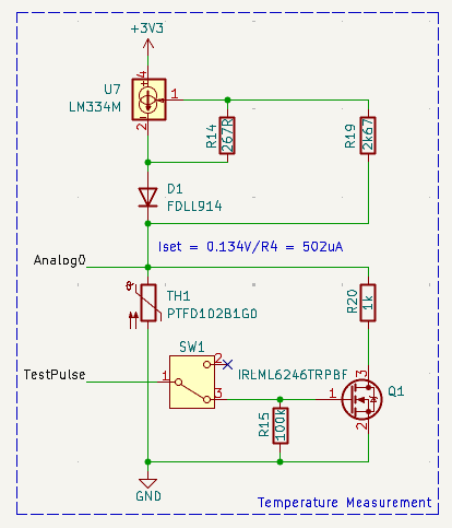
Our Processor-in-the-Loop hardware does not contain this temperature measurement hardware. Instead all the RP2040 inputs and outputs are connected to the test system as shown in the DUT schematics. Lets assume the test system outputs a static voltage of 0.55V on Analog0 and starts the firmware.
0.55V resembles about 1100 ohm resistance which in turn would be the resistance of our PT1000 sensor for a temperature of around 26°C.
When the firmware runs on the test system, it will immediately detect a hardware fault (because Analog0 does not change when the test pulse is applied).
With an active hardware fault, the temperature is never send via CAN. Our test goal was to test this temperature sending. What to do?
Simulating the hardware
The solution is to simulate the external hardware behavior. We use the ExecutionPlatform System Endpoint for that. This endpoint allows us to load a user-defined python model to the ExecutionPlatform. This simulation will run in parallel to the test sequence.
Our goal with this simulation is to
- Detect the start of a test pulse
- Calculate and set the
Analog0voltage by taking into account the parallel 1k test resistor. - Detect the end of a test pulse.
- Set the
Analog0voltage back to its normal value.
The system endpoint works by registering callback for pin changes and implement the desired actions in this callback.
In our case, we need a callback for the rising and falling edge of GPIO0, which is the RP2040 pin in RedAlert where the TestPulse signal is coming from.
import redalert as config

class SystemModel(config.Configuration):
    def __init__(self):
        self.outputs = {}
        self.simulated_temp = 20.0
        self.pulse_test_active = False

    def update_pt1000_voltage(self):
        # Formula for PT1000 based on temperature T
        # https://www.mouser.de/datasheet/2/418/6/ENG_DS_PTF_FAMILY_A3-775357.pdf
        # R(T) = R(0) * (1+a * T + b * T 2) ~ R(0) * (1+a*T)
        R0 = 1000
        a = 3.9083E-03
        # b = -5.775E-07

        r_pt1000 = R0 * (1 + a * self.simulated_temp)

        if self.pulse_test_active:
            r_test = 1e3
            r = (r_pt1000 * r_test) / (r_pt1000 + r_test)
        else:
            r = r_pt1000

        i = 502e-6
        u = r * i
        self.ANOUT0.Set_Static(f"{u}V")

    def enable_sink_test(self):
        self.pulse_test_active = True
        self.update_pt1000_voltage()

    def disable_sink_test(self):
        self.pulse_test_active = False
        self.update_pt1000_voltage()

    def start(self):
        self.GPIO0.on_rising(self.enable_sink_test)
        self.GPIO0.on_falling(self.disable_sink_test)
        self.update_pt1000_voltage()
Writing the test
We load this model to the ExecutionPlatform and start it in the robot test in line 13. It will then run continuously in parallel to the test sequence.
*** Settings ***
Library        ${ep_app_dir}/EP.py   ${ep_url}    ${ep_binary_dir}/redalert.ep-config
Suite Setup    Initial Setup
Test Setup     Each Test Setup

*** Keywords ***
Initial Setup
    DUT Flash Firmware    ${ep_binary_dir}/example/redalert_firmware.bin    wait_for_app_loaded=${False}
    DUT Power Off

Each Test Setup
    DUT Power Off
    CAN1 Start    Bitrate=500kbit/s
    Analog0 Set Static    0.55V  # PT1000(26°) = 1100 Ohm ~ 0.55 V
    System Start Model    ${CURDIR}/pt1000_model.py
    DUT Power On    wait_for_app_loaded=${False}
    Sleep    0.1s

*** Test Cases ***
Receive a frame immediately after start
    ${tempFrames} =     CAN1 Get Frames
    Length Should Be    ${tempFrames}    1

Receive a second frame after 1s
    Sleep    1.0s
    ${tempFrames} =     CAN1 Get Frames
    Length Should Be    ${tempFrames}    2

First and Second CAN Frames are sent within 1s +/- 5%
    CAN1 Wait For Frame Buffer    ExpectedCount=2    Timeout=3.5s
    ${frames} =     CAN1 Get Frames
    FOR  ${frame}    IN    @{frames}
        Log To Console    ${frame.time}
    END

    ${diff1} =    Evaluate    ${frames[1].time} - ${frames[0].time}
    Should Be True    0.95 < ${diff1} < 1.05
Running the test
With the active simulation, the tests pass. We now have a running system test for our unmodified RedAlert firmware. This Processor-in-the-Loop test ensures that all effects of the firmware are effectively tested.
==============================================================================
System.Firmware
==============================================================================

Programming MCU...
Receive a frame immediately after start                               | PASS |
------------------------------------------------------------------------------
Receive a second frame after 1s                                       | PASS |
------------------------------------------------------------------------------
First and Second CAN Frames are sent within 1s +/- 5%                 ...
0.29047743

1.29076436
First and Second CAN Frames are sent within 1s +/- 5%                 | PASS |
------------------------------------------------------------------------------
System.Firmware         | PASS |
3 tests, 3 passed, 0 failed
==============================================================================
Using the Analyzer Endpoint we can capture all relevant signals for a visual representation. Running the firmware for a few seconds with simulation enabled gives us the result below.
Recall that GPIO0.Pin is changed by the firmware and the level change in ANOUT0.Pin is caused by the model reacting to the active pulse.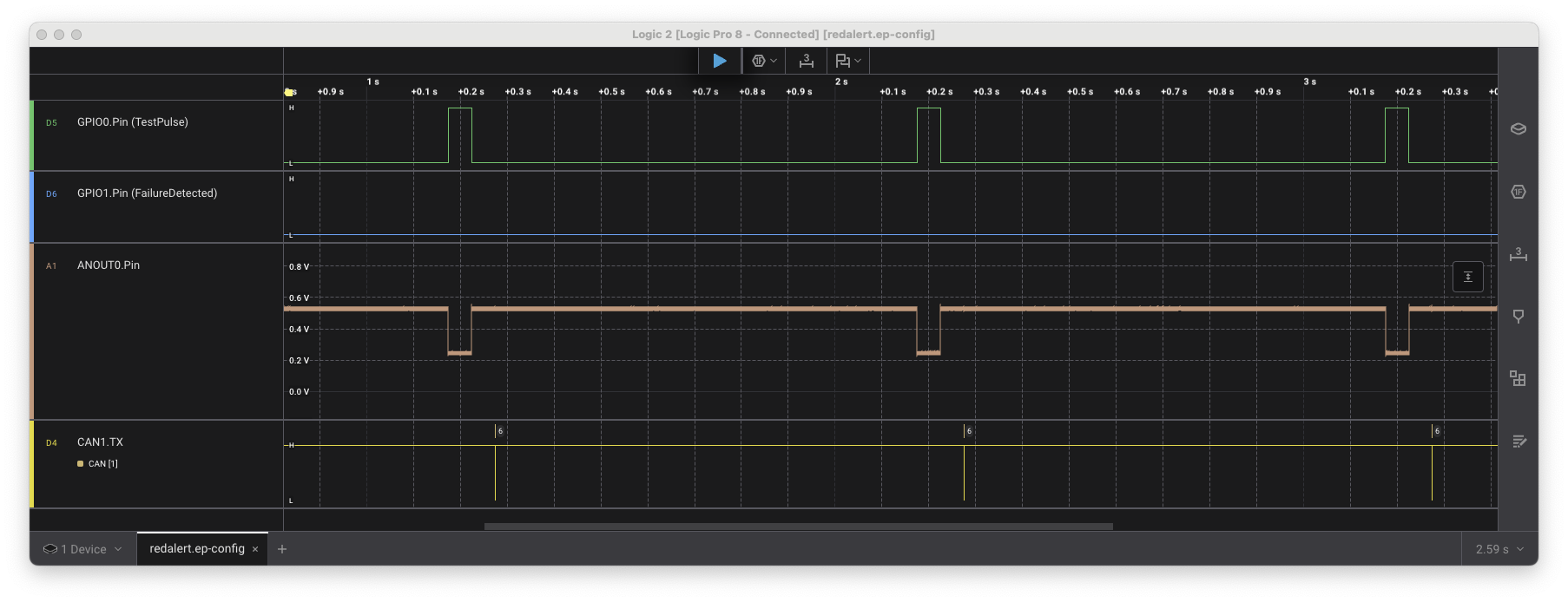
From this starting point, it is very easy to test more advanced use cases. For example the python model could be instructed to ignore the test pulse for a given time - reflecting a hardware fault that is difficult to test with real hardware.