Imagine the following scenario: You need to create a highly precise pulse on a microcontroller GPIO pin. The pulse needs to be within 1% of the desired value. This article shows you, how to compare two variations of a driver against these requirements easily using the power of Open Loop Testing.

You want to use the ST stm32u575zi, which is from now on going to be called DUT (Device Under Test). PB10 is going to be the pin of choice. It should be pulled to GND when inactive.

Structure

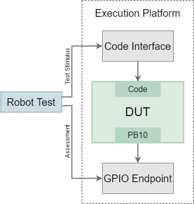
The test to be implemented is an Open Loop test and structured in the following way: The ExecutionPlatform represents the test system housing the Code Interface and the GPIO Endpoint. The ExecutionPlatform (EP) also contains the DUT itself. Both stimulus and assessment are done by a Robot-Framework test suite. This suite is controlling the test process.
To begin testing, a stimulus is sent from the Robot test suite to the EP Code Interface. This then invokes a method on the DUT, which creates the pulse with desired length. All of this can be done simply by using the Robot keyword DUT Invoke    <method>    <arg1...> (Look here for more Information).

The GPIO Endpoint measures the pulse length and sends the results back to the test suite as soon as they are requested. The Robot suite then checks the results.

Contestants

You want to test two variations of a driver. Both are able to create a single pulse on PB10 on demand with a given length.

The first variant tackles this task in a rather simple way: PB10 is used as a simple GPIO-Pin, which is reset by default. When the pulse starts, PB10 is set and one of the DUT’s hardware timers starts counting. The timers count register is continuously polled. When the count register reaches the desired pulse length, PB10 is reset and the timer stops counting.

The second variant utilizes one of the DUT’s timers PWM mode. By setting period and duty-cycle to the correct values, it is easy to create a PWM-waveform consisting of pulses with the desired pulse length. The waveform generation has to be stopped after the first pulse, since we only want to create a single pulse. This can be done with an interrupt that is called whenever a pulse finishes.

Since the second variant uses a hardware feature to achieve the desired outcome, we are from now on going to refer to it as the “hardware variant”, while the first variant is going to be called “software variant”.

Enough theory, let’s start testing! From now on, we are basically going to follow the documentation Basic Usage.

Software Variant

Includes

To use the EP features, the ep core file needs to be included. Refer to Basic Usage – Create a binary for more information.

create_pulse Function

The following paragraph describes the function used to generate the pulse. This function is called create_pulse() and needs to be callable from the Robot test suite via the Code Interface. For this, it needs to fulfill two requirements:

    1. It must be registered using the ep_register() method in ep_app_main(). We are going to take care of this later on.
    2. It must match the signature int32_t(uint8_t const* payload, int len).

Every function callable in this way receives two parameters: uint8_t const* payload and int len. The first parameter points to an array in memory containing the data the function was invoked with in Robot. The second parameter describes the length of this array (See Basic Usage – Code Interface for more information). In our case, the only content of this data is a string representation of the desired pulse length in us. The function converts this string into an integer (uint16_t duration_us) and calculates the number of ticks the timer has to make, until the pulse needs to end (uint16_t duration_ticks). It then sets PB10 and starts the timer. After waiting until the timers count register (TIM2->CNT) reaches duration_ticks, it resets PB10 and stops the timer.

Main Function

You surely have noticed already, that the main function in this file is not the typical int main()entry point, but instead int ep_app_main().  This is because the “actual” main() function is located somewhere in the Board Support Package (BSP). The function ep_app_main() is called automatically by the BSP and has to be provided by you.
In our case, all that needs to be done in ep_app_main() are the following actions:

    1. Configure and enable PB10 as a GPIO-Pin
    2. Reset PB10
    3. Configure and enable the timer

Additionally, the create_pulse() function is registered, so it is callable from Robot. This is done using ep_register("create_pulse", &create_pulse);. The first parameter specifies, under which name the function will be registered. This ID will be used to invoke create_pulse() from within the Robot test suite. The second parameter is just a pointer to the corresponding function. For more Information on registering functions, refer to: Basic Usage – Create a binary.

A small example: Calling Dut Invoke    create_pulse    500 in the Robot tests suite would now cause the DUT to create a pulse lasting 500us on PB10. It’s as easy as that!

The last command of ep_app_main() should always be return ep_process_loop();. This starts the loop used to process invocations sent from Robot.

Code


#include <ep/core.h>
#include "ep_internal_haldef.h"
#include <cstdlib>
#include <cstring>

TIM_HandleTypeDef htim2;

static constexpr int sysFreq_MHz = 25;
static constexpr int timPrescale = 25;      // Note: DUT runs @ 25MHz => every tick is 1us
static constexpr int timPeriod = 50000;     // max number of ticks a pulse can last

int32_t create_pulse(uint8_t const* payload, int len) {
    // Expected payload format: <duration_us>
    //
    // Creates a single pulse lasting us on PB10 
    char duration_cstring[10] = {0};
    memcpy(duration_cstring, payload, len);
    uint16_t duration_us = atoi(duration_cstring);
    uint16_t duration_ticks = (sysFreq_MHz/timPrescale)*duration_us;

    // Set PB10 and start the timer
    HAL_GPIO_WritePin(GPIOB, GPIO_PIN_10, GPIO_PIN_SET);
    TIM2->CNT = 0;
    HAL_TIM_Base_Start(&htim2);

    // Wait until duration_us us have passed
    while (TIM2->CNT < duration_ticks){
        asm volatile("nop");
    }

    // Reset PB10 and stop the timer
    HAL_GPIO_WritePin(GPIOB, GPIO_PIN_10, GPIO_PIN_RESET);
    HAL_TIM_Base_Stop(&htim2);

    return 0;
}

int ep_app_main() {
    __HAL_RCC_GPIOB_CLK_ENABLE();

    // Configure and enable PB10 as output
    GPIO_InitTypeDef GPIO_InitStruct;
    GPIO_InitStruct.Pin = GPIO_PIN_10;
    GPIO_InitStruct.Mode = GPIO_MODE_OUTPUT_PP;
    GPIO_InitStruct.Speed = GPIO_SPEED_HIGH;
    GPIO_InitStruct.Pull = GPIO_PULLDOWN;
    GPIO_InitStruct.Alternate = 0;
    HAL_GPIO_Init(GPIOB, &GPIO_InitStruct);

    // Reset PB10
    HAL_GPIO_WritePin(GPIOB, GPIO_PIN_10, GPIO_PIN_RESET);

    // Configure and enable TIM2
    __HAL_RCC_TIM2_CLK_ENABLE();
    htim2.Instance = TIM2;
    htim2.Init.Prescaler = timPrescale-1;
    htim2.Init.CounterMode = TIM_COUNTERMODE_UP;
    htim2.Init.Period = timPeriod;
    if (HAL_TIM_Base_Init(&htim2) != HAL_OK){
        ep_abort("TIM error");
    }
    TIM_MasterConfigTypeDef sMasterConfig;
    sMasterConfig.MasterOutputTrigger = TIM_TRGO_RESET;
    sMasterConfig.MasterSlaveMode = TIM_MASTERSLAVEMODE_DISABLE;
    if (HAL_TIMEx_MasterConfigSynchronization(&htim2, &sMasterConfig) != HAL_OK){
        ep_abort("TIM error");
    }

    // Make 'create_pulse' function callable from Robot sequence
    ep_register("create_pulse", &create_pulse);

    return ep_process_loop();
}

Test Suite

All that is missing to begin the actual test of the first driver, is the test itself. The test is written using the Robot Framework.

To access the EP functionality, add the EP.resources file as a resource. For more information, please refer to Basic Usage – Write Robot Tests.

The respective binary can be flashed to the DUT from Robot using the keyword Dut Flash Firmware    <path>, where <path> is the path to the binary that should be flashed.

In order to prevent the EP to drive against the DUT on PB10, we want to set PB10 to a high impedance on the EP side. For this, the keyword PB10 Set Tristate can be used. Since both of these things should happen at the setup of the test suite, they are grouped in a single keyword named Setup. This keyword is set to be executed whenever the Robot suite is started: Suite Setup       Setup

Each test first instructs the GPIO-Endpoint to start a measurement on PB10.
Then it invokes the create_pulse() function on the DUT. The first test uses a pulse length of 7µs. The measurement result is retrieved from the GPIO-Endpoint and assessed.

And that’s all there is to the test! The test sequence can be started now by pressing the F1 key and executing the command Robot Framework: Run Test/Task Suite.


*** Settings ***
Resource         EP.resource
Suite Setup      Setup
Documentation    Checks that DUT driver produces precise pulses.

*** Keywords ***
Check That Within 1% Tolerance
    [Arguments]    ${expected}    ${actual}
    ${tolerance_percent} =    Set Variable    1
    ${tolerance_absolute} =    Evaluate    ${tolerance_percent}*${expected}/100
    ${expected_lower} =    Evaluate    ${expected} - ${tolerance_absolute}
    ${expected_upper} =    Evaluate    ${expected} + ${tolerance_absolute}
    Should Be True    ${actual} > ${expected_lower} and ${actual} < ${expected_upper}    Actual value (${actual}) out of tolerance for expected value (${expected}).

Setup
    DUT Flash Firmware    ${ep_binary_dir}/example/generic/example_generic_pulses_software.bin
    PB10 Set Tristate

*** Test Cases ***
Long 7ms Pulse Is Within 1% Tolerance
    # 1. Prepare a measurement of a single pulse on PB10 (pulse started by rising, stopped by falling edge)
    GPIO Measure Between Rising And Falling Edge    PB10    PB10

    # 2. Invoke function on DUT that produces a 7000us long pulse
    DUT Invoke    create_pulse    7000

    # 3. Read back the measured pulse
    ${measured_length_us} =     GPIO Get Measurement Result In Microsecond

    # 4. Check that measurement result is within 1% bounds
    Check That Within 1% Tolerance    7000    ${measured_length_us}

Short 600us Pulse Is Within 1% Tolerance
    GPIO Measure Between Rising And Falling Edge    PB10    PB10
    DUT Invoke    create_pulse    600
    ${measured_length_us} =     GPIO Get Measurement Result In Microsecond
    Check That Within 1% Tolerance    600    ${measured_length_us}

Very Short 50us Pulse Is Within 1% Tolerance
    GPIO Measure Between Rising And Falling Edge    PB10    PB10
    DUT Invoke    create_pulse    50
    ${measured_length_us} =     GPIO Get Measurement Result In Microsecond
    Check That Within 1% Tolerance    50    ${measured_length_us}

Results (Software Variant)

After executing the Robot suite for the software variant using the previously mentioned command, we can find the following result in VS Codes integrated command line:

==============================================================================
Pulses Are Precise :: Checks that DUT driver produces precise pulses.
==============================================================================
Long 7ms Pulse Is Within 1% Tolerance                                 | PASS |
------------------------------------------------------------------------------
Short 600us Pulse Is Within 1% Tolerance                              | PASS |
------------------------------------------------------------------------------
Very Short 50us Pulse Is Within 1% Tolerance                          | FAIL |
Actual value (52.83) out of tolerance for expected value (50).
------------------------------------------------------------------------------
Pulses Are Precise :: Checks that DUT driver produces precise pulses. | FAIL |
3 tests, 2 passed, 1 failed
==============================================================================
Output:  C:\Users\josch\embeff\ep\output.xml
Log:     C:\Users\josch\embeff\ep\log.html
Report:  C:\Users\josch\embeff\ep\report.html

Its obvious that the software variant is not sufficiently precise. The pulse created by this driver seems to be always 2~4us longer than desired. This error clearly exceeds the required tolerance of 1% for some pulse lengths. But let's not give up and crack on with the hardware variant!

Hardware Variant

Since both variants of the driver follow the same structure, we are just going to quickly gloss over the differences.

create_pulse Function

After converting the desired pulse length into an integer (duration_us), a helper function is called. This helper function reinitializes the timers PWM-Mode to accommodate for the new desired pulse length. After that, the timer is reset and the PWM-generation is started.

The PWM-generation should be stopped, after the first pulse finishes. Due to the way the timer is set up in this case, this is when the timers period elapses for the first time. Luckily, there is an interrupt for that. The HAL provides a callback for this interrupt: HAL_TIM_PeriodElapsedCallback. Whenever this callback is invoked, the PWM generation is stopped immediately by calling HAL_TIM_PWM_Stop_IT().

Main function

Like in the first variant, the ep_app_main() function just needs to initialize all the components that are going to be used. Namely:

  1. Configure and enable the timer
  2. Enable NVIC-interrupts for the timer
  3. Initialize PB10

Just like before, the create_pulse() function gets registered at the end using ep_register("create_pulse", &create_pulse); and the ep_app_main() function ends with return ep_process_loop();.

Code


#include <ep/core.h>
#include <cstdlib>
#include <cstring>
#include "ep_internal_haldef.h"

TIM_HandleTypeDef htim2;

static constexpr int sysFreq_MHz = 25;
static constexpr int timPrescale = 5;       // Note: DUT runs @ 25MHz => every tick is 1/5us
static constexpr int timPeriod = 250000;    // max number of ticks a pulse can last

void initPWM(int duration_us){
    // (re-)initializes PWM for TIM2
    TIM_OC_InitTypeDef sConfigOC;
    sConfigOC.OCMode = TIM_OCMODE_PWM2;         // Channel 3 is active as long as Counter > Pulse
    sConfigOC.Pulse = timPeriod-((sysFreq_MHz/timPrescale)*duration_us);
    sConfigOC.OCPolarity = TIM_OCPOLARITY_HIGH;
    sConfigOC.OCFastMode = TIM_OCFAST_DISABLE;
    if (HAL_TIM_PWM_ConfigChannel(&htim2, &sConfigOC, TIM_CHANNEL_3) != HAL_OK){
        ep_abort("TIM2 OC Config Error");
    }
    if (HAL_TIM_PWM_Init(&htim2) != HAL_OK){
        ep_abort("TIM2 PWM Init Error");
    }
}

int32_t create_pulse(uint8_t const* payload, int len) {
    // Expected payload format: <duration_us>
    //
    // Creates a single pulse lasting us on PB10 
    char duration_cstring[10] = {0};
    memcpy(duration_cstring, payload, len);
    int duration_us = atoi(duration_cstring);

    initPWM(duration_us);

    TIM2->CNT = 0;

    // Check and set the TIM channel state
    if (TIM_CHANNEL_STATE_GET(&htim2, TIM_CHANNEL_3) == HAL_TIM_CHANNEL_STATE_READY){
        TIM_CHANNEL_STATE_SET(&htim2, TIM_CHANNEL_3, HAL_TIM_CHANNEL_STATE_BUSY);
    } else {
        return -1;
    }
    
    // Enable Period Elapsed Interrupt
    __HAL_TIM_ENABLE_IT(&htim2, TIM_IT_UPDATE);

    // Enable the Capture compare channel
    TIM_CCxChannelCmd(htim2.Instance, TIM_CHANNEL_3, TIM_CCx_ENABLE);

    // Enable Timer
    __HAL_TIM_ENABLE(&htim2);

    return 0;
}

extern "C" {
    void TIM2_IRQHandler(void){
        HAL_TIM_IRQHandler(&htim2);
    }

    void HAL_TIM_PeriodElapsedCallback(TIM_HandleTypeDef*){
        HAL_TIM_PWM_Stop_IT(&htim2, TIM_CHANNEL_3);
    }
}

int ep_app_main() {
    // Disable the internal Pull-Up in Dead Battery pins of UCPD peripheral
    HAL_PWREx_DisableUCPDDeadBattery();

    // Enable TIM2 Clock
    __HAL_RCC_TIM2_CLK_ENABLE();

    // Enable NVIC-Interrupts for TIM2
    HAL_NVIC_SetPriority(TIM2_IRQn, 1, 0);
    HAL_NVIC_EnableIRQ(TIM2_IRQn);
    
    // Initialize TIM2 except PWM
    htim2.Instance = TIM2;
    htim2.Init.Prescaler = timPrescale-1;
    htim2.Init.CounterMode = TIM_COUNTERMODE_UP;
    htim2.Init.Period = timPeriod;
    htim2.Init.ClockDivision = TIM_CLOCKDIVISION_DIV1;
    htim2.Init.AutoReloadPreload = TIM_AUTORELOAD_PRELOAD_ENABLE;
    if(HAL_TIM_Base_Init(&htim2) != HAL_OK){
        ep_abort("TIM2 Init Error");
    }
    TIM_MasterConfigTypeDef sMasterConfig;
    sMasterConfig.MasterOutputTrigger = TIM_TRGO_RESET;
    sMasterConfig.MasterSlaveMode = TIM_MASTERSLAVEMODE_DISABLE;
    if (HAL_TIMEx_MasterConfigSynchronization(&htim2, &sMasterConfig) != HAL_OK){
        ep_abort("TIM2 Master Config Error");
    }

    // Set Clock Source for TIM2
    TIM_ClockConfigTypeDef sClockSourceConfig;
    sClockSourceConfig.ClockSource = TIM_CLOCKSOURCE_INTERNAL;
    if (HAL_TIM_ConfigClockSource(&htim2, &sClockSourceConfig) != HAL_OK){
        ep_abort("TIM2 Clock-Source Init Error");
    }

    // Init GPIO-Pin
    __HAL_RCC_GPIOB_CLK_ENABLE();
    GPIO_InitTypeDef GPIO_InitStruct;
    GPIO_InitStruct.Pin = GPIO_PIN_10;
    GPIO_InitStruct.Mode = GPIO_MODE_AF_PP;
    GPIO_InitStruct.Pull = GPIO_PULLDOWN;
    GPIO_InitStruct.Speed = GPIO_SPEED_FREQ_VERY_HIGH;
    GPIO_InitStruct.Alternate = GPIO_AF1_TIM2;
    HAL_GPIO_Init(GPIOB, &GPIO_InitStruct);

    // Make 'create_pulse' function callable from Robot sequence
    ep_register("create_pulse", &create_pulse);
    return ep_process_loop();
}

Results (Hardware Variant)

Since both drivers follow the same structure, the exact same Robot suite can be reused for the hardware variant. The only thing that needs to be changed, is the binary to be flashed. After executing the Robot suite again, the results look more promising:

==============================================================================
Pulses Are Precise :: Checks that DUT driver produces precise pulses.
==============================================================================
Long 7ms Pulse Is Within 1% Tolerance                                 | PASS |
------------------------------------------------------------------------------
Short 600us Pulse Is Within 1% Tolerance                              | PASS |
------------------------------------------------------------------------------
Very Short 50us Pulse Is Within 1% Tolerance                          | PASS |
------------------------------------------------------------------------------
Pulses Are Precise :: Checks that DUT driver produces precise pulses. | PASS |
3 tests, 3 passed, 0 failed
==============================================================================
Output:  C:\Users\josch\embeff\ep\output.xml
Log:     C:\Users\josch\embeff\ep\log.html
Report:  C:\Users\josch\embeff\ep\report.html

The hardware variant of the driver meets every requirement.

Conclusion

This article compared two implementations of the same driver against certain requirements. The results showed quickly, which driver was sufficiently precise and thus met the requirements, and which wasn't.

Doing this turned out to be quite easy. This demonstrates the fundamental power of Open Loop Testing.
You can try out this and other examples right now in your browser.