Unit, Integration and System Testing for embedded teams.
The ExecutionPlatform: A PiL test system for microcontroller code.
Test your code against physical pin behavior.
HiL confidence without HiL cost.
No cabling. Reconfigure pin usage for each test.
Try it for free in the browserYour microcontroller as a test object
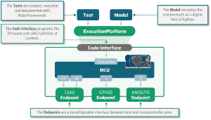
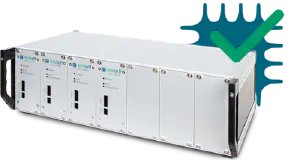
The ExecutionPlatform is a generic Processor-in-the-Loop test system to which your microcontroller is connected as a plug-in board.
This board makes pins and programming interface accessible to the test system.

A single test system for unit, integration & system tests
Write unit tests
Test individual functions, classes or modules. With the Code Interface, you can easily flash and start your unit tests on the microcontroller. The results are conveniently prepared and evaluated on the PC. Using a built-in benchmark function, you can ensure that the timing behavior meets your requirements.
Ready-made support for GoogleTest, Unity, Catch2.
No need to run on PC with another compiler.
Permanently check timing behavior for critical paths.
See unit testing in action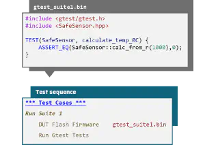
Write hardware/software integration tests
HW/SW integration tests check the interaction between hardware-dependent code and the physical pin level of the microcontroller. Using Endpoints, you start processes on the pins or evaluate processes started by the microcontroller. This might be setting/reading a GPIO pin or sending/receiving a CAN frame.
Tests use the Code Interface to execute a function on the microcontroller and thus trigger the behavior to be tested on the pins. This behavior is then automatically checked using the appropriate endpoint.
Reproducibility guaranteed through automation.
Easily check error states.
Prove coverage for drivers/HAL.
See integration testing in action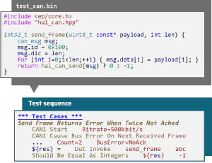
Write system tests
Traditional system tests use complex HiL systems that test the product at the outer limits of the circuit board. The ExecutionPlatform offers an innovative and practical alternative that can already be used in the early development phase.
A Model simulates the microcontroller’s environment on the pins. Endpoints can trigger one-off or regular events on the pins. The model uses callbacks to respond to events initiated by the microcontroller.
System tests during development.
Digital twin of the environment via model.
Real-time capability guaranteed.
See system tests in action
Get your powerful environment for HW/SW integration tests.
1 | Integrate your microcontroller. 
Use up to 24 Analog Outputs. |
2 | You choose ExecutionPlatform hardware for your needs.  Standalone One microcontroller. Use it on your desk. 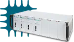 Rack Different microcontrollers. Multiple parallel users. Mountable in your 19" rack.  Hosted We host the hardware. Scales to your needs. Secure access from anywhere. |
3 | You choose a package for your needs. Unit Everything to write unit tests and benchmarks. Code Interface GPIO + Analyzer Endpoint Quick Email support Continuous software updates Free hardware upgrade for new EP-generations Integration Hardware/Software integration tests for all your periphery. Everything in "Unit" All peripheral Endpoints Powerful ways for fault injection System Agile system tests during development. Everything in "Integration" All simulation Endpoints Digital Twin models to simulate environment Test your production firmware |
Why customers choose us
Stable Firmware
Innovative Open Loop Tests that let you write robust drivers.
Easily check error scenarios that are otherwise hard-to-test.
100% automated. No cabling necessary.
Support for all common periphery such as UART, SPI or CAN.

Productive work. From anywhere
View any of your microcontroller pins to gain insights.
Use it from anywhere. You only need a network connection.
Debugger, Oscilloscope, Signal Generator and Microcontroller PCB combined into a single device.

Focus on your core business
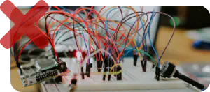
No more self-made solutions that are impossible to maintain.
Solid documentation so that everyone can use it.
Fast onboarding. For everyone.
Scales to your budget
10x cost reduction compared to a typical HiL system.
Flexible monthly licensing. Pay only for what you need.
Details
Test Sequences
We like to use software that works excellently. Especially if it is an open source solution that is already being used successfully in leading industrial companies: The Robot Framework.
The functions of the ExecutionPlatform can be used entirely from the Robot Framework. In your test sequences you use our endpoints and the code interface.
You have little time for cumbersome tool setup. Therefore we offer a completely preconfigured integration into the most modern IDE in the world: Visual Studio Code.

Full Automation
Endpoints replace your laboratory devices
Endpoints are the interface between test and periphery. Each endpoint supports a specific periphery (GPIO, CAN, …).
The periphery can refer to one or more arbitrary MCU pins. Endpoints can be configured as required on the ExecutionPlatform. All pins of your microcontroller are available for this.
Checking or stimulating pins is traditionally done manually using an oscilloscope and signal generator. The functions of these devices are already integrated in the endpoints. No additional devices are necessary.
Code Interface to access your functions
Functions on the microcontroller are called at runtime via the code interface.
You register the functions you want to call in the firmware. These functions can then be conveniently called from the test sequence.
A debug probe is already integrated so that your firmware can be transferred to the built-in microcontroller. Flashing is conveniently done from the test sequence.
Specific questions?
Take a look at our FAQ.
Learn more in our monthly webinar. With room for your questions.